![]()
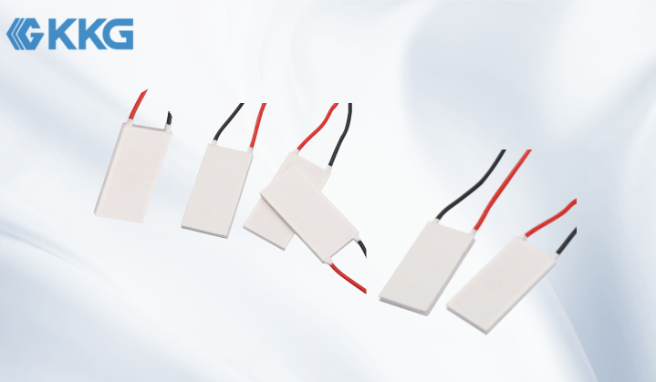
Product Structure of Thermoelectric Cooler
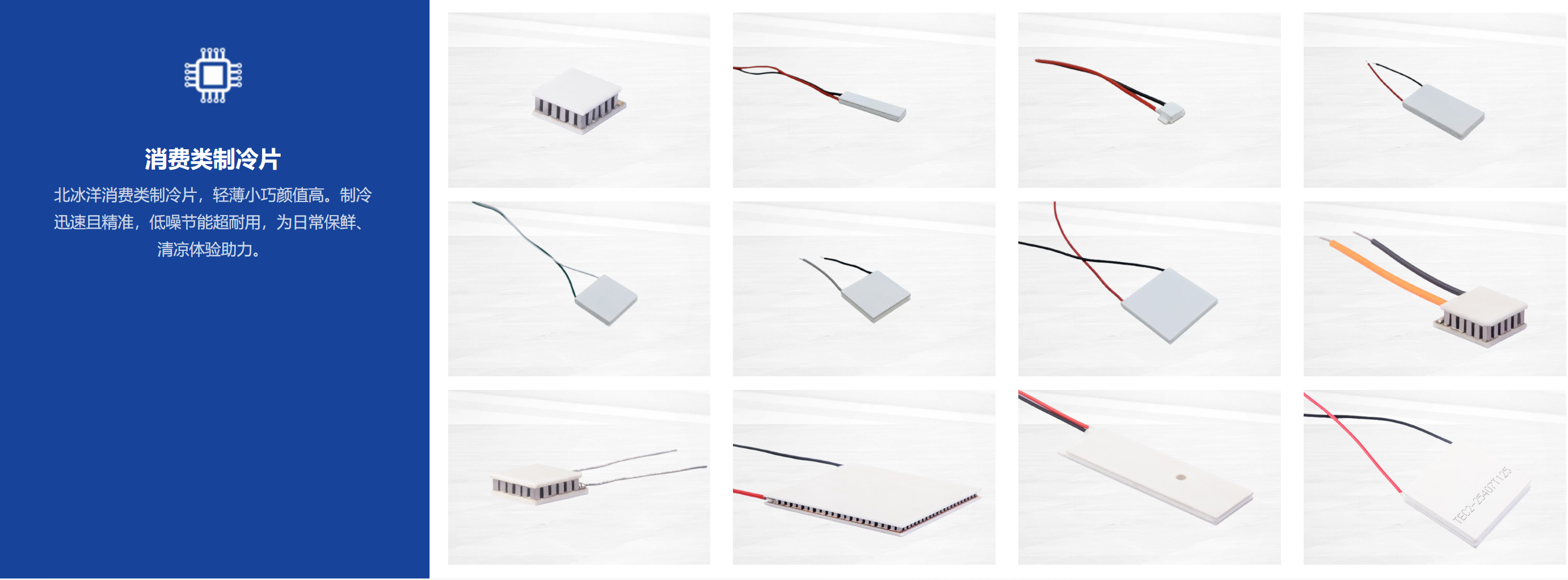
A thermoelectric cooling module is a solid-state semiconductor heat pump. Tec cooler's core structure consists of a multi-layer ceramic substrate sandwiching a series-connected array of thermocouples. From the inside out, Thermoelectric cooler peltier can be divided into the following key layers:
1. Top Ceramic Substrate of peltier effect cooler:
• Material: Aluminum oxide (Al₂O₃) ceramic. This is the most common choice, offering excellent insulation, thermal conductivity, and mechanical strength.
• Function: Forms the heat dissipation interface at the cold end and must be in close contact with the object to be cooled (e.g., CPUs, lasers) to efficiently absorb heat.
2. Top Electrode of peltier cooling module:
• Located beneath the ceramic substrate, made of copper or a copper alloy, and used to connect N-type and P-type semiconductor thermoelectric arms in series.
3. Thermocouple Array of cooler with peltier:
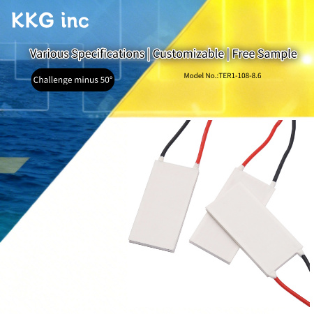
• Core component. Consists of hundreds of pairs (e.g., the “108” in model TEC1-108-8.6 indicates 108 pairs) of tiny semiconductor blocks connected in series via metal electrodes.
• P-type thermocouple: Made of a semiconductor material (e.g., Bi₂Te₃) formed by doping, with “holes” as the charge carriers.
• N-type thermoelectric elements: Made from semiconductor materials (such as Bi₂Te₃) doped to have “electrons” as the charge carriers.
• Configuration: N-type and P-type blocks are connected in series electrically but arranged in parallel physically. They are filled with low-thermal-conductivity, high-insulation materials to provide thermal insulation.
4. Bottom Electrode of peltier device cooler:
• Located beneath the thermoelectric element array, it has the same structure as the top electrode and serves to connect to the other terminal of the circuit.
5. Bottom Ceramic Substrate of peltier module cooler:
• Has the same structure as the top substrate.
• Function: Forms the heat dissipation interface for the hot end and must be tightly connected to an external cooling system (such as a heat sink + fan) to dissipate heat.
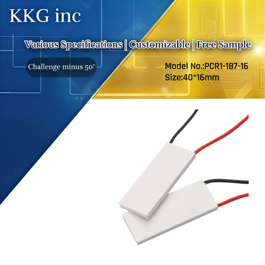
The overall structure can be summarized as follows: Two ceramic plates sandwich the series-connected N/P-type semiconductor thermoelectric arm arrays, forming a “thermoelectric sandwich.”thermoelectric peltier device's dimensions of 40 × 20 mm and ultra-thin thickness of 3.15 mm are determined by the number and size of the internal thermoelectric arms, as well as the thickness of the ceramic substrates.
![]()
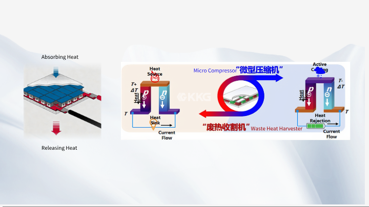
Working Principle of Peltier Device
The core physical principle behind thermoelectric cooling modules is the Peltier effect, which is the reverse of the Seebeck effect (the principle behind thermocouple temperature measurement).
In a nutshell: When a direct current flows through a circuit composed of two different semiconductor materials (n-type and p-type), heat is either absorbed or released at the junction between the two materials.
1. Applying Power Creates a Temperature Difference:
• When a DC power source is connected to the positive and negative terminals of the cooling element, current (as shown in the figure) flows from the external power source, passing sequentially through the N-type and P-type semiconductors.
• At each junction where the current flows between a metal electrode and the semiconductor, heat is transferred.
2. Formation of the Cold End and Hot End:
• At the top (cold end): Current flows from the N-type arm through the electrode into the P-type arm. At this junction, charge carriers (electrons and holes) must absorb additional energy to “jump” over the energy barrier, thereby absorbing heat from the junction and causing the junction temperature to drop. This process of heat absorption at the cold end is known as cooling.
• At the bottom (hot end): Current flows from the P-type arm through the electrode into the N-type arm. At this junction, carriers (holes and electrons) release excess kinetic energy, thereby releasing heat at the junction and causing the junction temperature to rise.
3. The “Pumping” Process of Heat:
• As current continues to flow, this process of heat absorption and release continues.
• As a result, heat is forcibly “pumped” from the top (cold end) of the heat sink to the bottom (hot end).
• To maintain cooling efficiency, the heat at the hot end must be dissipated into the environment promptly and efficiently by an external cooling system (heatsink + fan). This is critical for the proper operation of the heat sink; otherwise, heat will accumulate and rapidly flow back to the cold end, causing the cooling system to fail or even burn out.


 Get A Free Quote