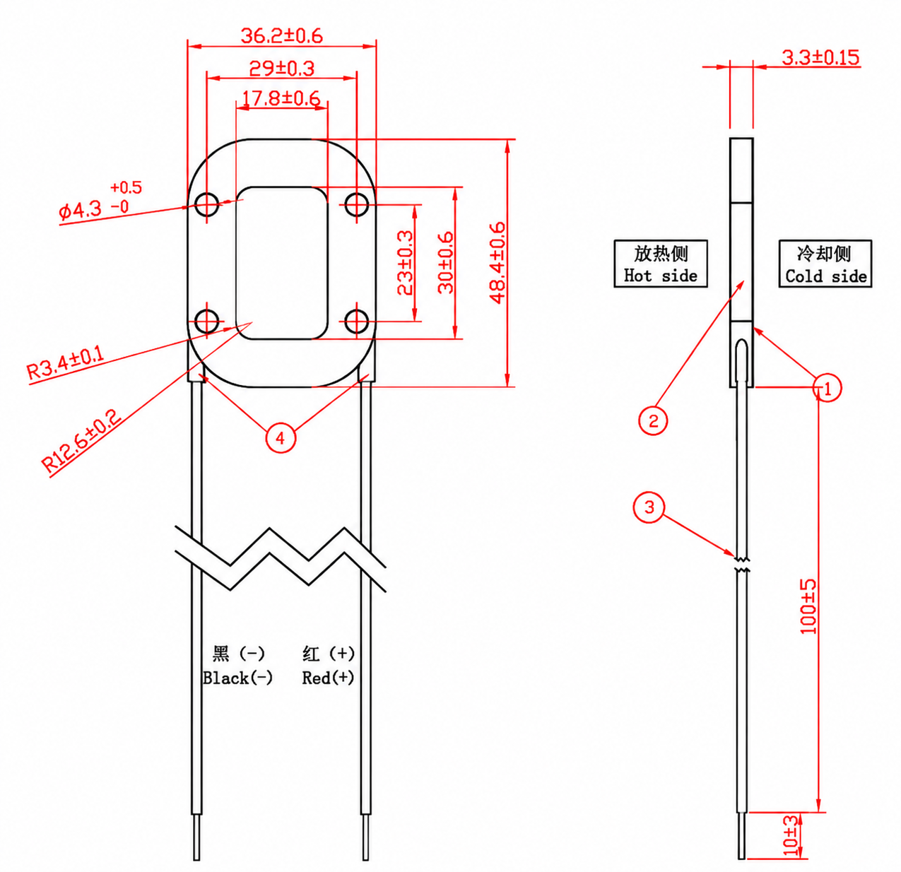
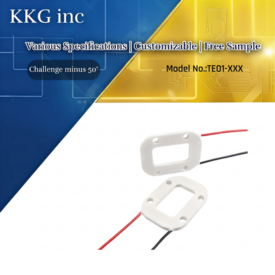
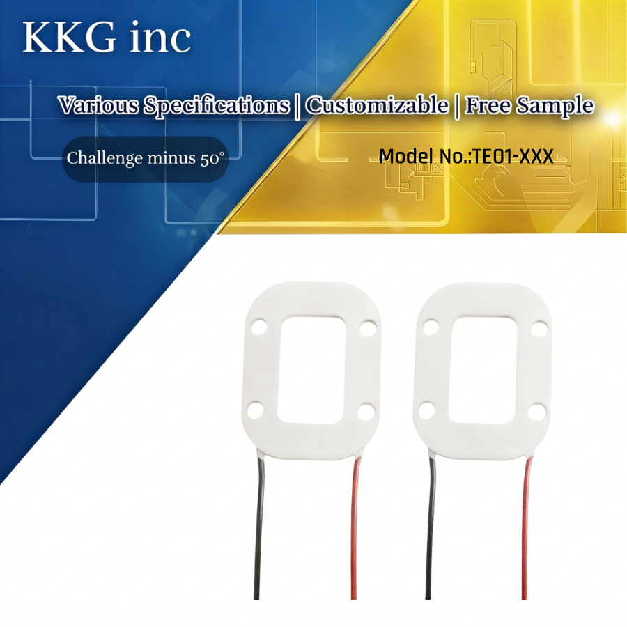
🔷Product Drawing
![]()
🔷 Product Materials
| Product | Thermo-module | Class | Outline drawing |
| No. | Item | Specification | |
| 1 | Ceramic plate | 96% Al₂O₃, white color | |
| 2 | Seal | Sealed with 703 RTV or equal between cold and hot ceramic plates | |
| 3 | Lead wire | AWG #22 or equivalent, Sn-plated on the surface, MAX Temperature: 105°C | |
| 4 | Joint of wire | Sealed with 703 RTV or equal at the joint of wire | |
🔷 Product Parameter
| Performance Parameters | Specification | Remarks |
| Resistance | 1.95Ω ± 10% | Note-1 |
| Max. Current (Imax) | 6.0 A | Note-2 |
| Max. Voltage (Vmax) | 14.0 V | Note-3 |
| Max. Heat Absorption (Qcmax) | | |
| Th=27°C | 50.8 W | Note-5 |
| Th=50°C | 56.0 W | Note-5 |
| Max. Temperature Difference (ΔTmax) | | |
| Th=27°C | 70 °C | Note-6 |
| Th=50°C | 77 °C | Note-6 |
| Solder Melting Point | 235 °C | Note-7 |
| Compression Strength | 1 MPa | Note-8 |
Notes (Remarks)
- Note-1: Measured by AC 4-terminal method at 25°C ambient temperature.
- Note-2: Input current resulting in the greatest temperature difference (ΔTmax).
- Note-3: Maximum DC input voltage at ΔTmax and Th=27°C.
- Note-4: Th indicates the temperature of the TEC hot side during operation.
- Note-5: Maximum amount of heat that can be absorbed at the cold side (occurs at I = Imax, ΔT = 0°C).
- Note-6: Maximum temperature difference a TEC can achieve (occurs at I = Imax, Qc = 0W). ΔTmax is measured in a vacuum chamber at 1.3 Pa.
- Note-7: Lowest melting point of solder used in the thermoelectric module.
- Note-8: Recommended maximum compressive stress per unit area (exceeding this limit may damage the module).
🔷 Product Feature
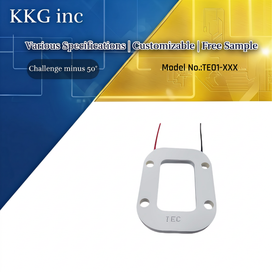
1. Unique hollow track-shaped design with a central opening, suitable for scenarios requiring “circular cooling + open center.”
2. Dimensions: 48.4 × 36.2 mm; Hollow area: 30 × 29 mm
3. 4 mounting holes (φ4.3 mm), thickness 3.3 mm, for a tighter fit.
4. Red (+) and black (-) leads, length 100±5 mm, clearly distinguishing the cold end from the hot end
5. Performance Focus: Outstanding deep-low-temperature capability, making it more suitable for professional applications requiring high cooling depth.
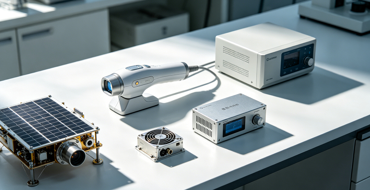
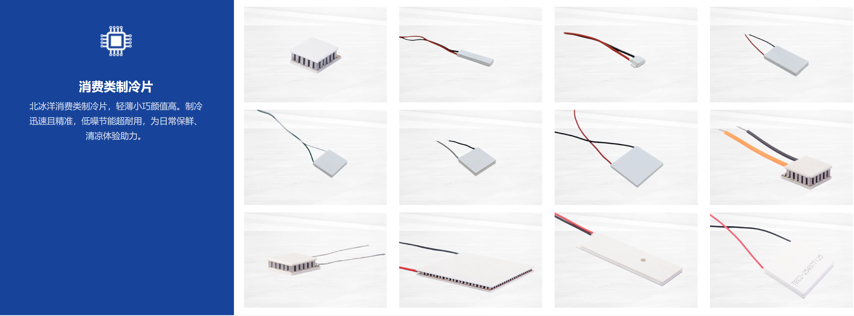
🔷 Product Application
![]()
1.Medical & Aesthetics: Laser hair removal, IPL devices (precision cooling for treatment heads, hollow structure fits optical paths); cryotherapy devices (localized cooling for pain relief).
2.Optics & Lasers: Laser modules, infrared detectors, CCD/CMOS sensors (ring-shaped design avoids blocking light paths, stabilizes component temperature); spaceborne/aerospace optical components (high-precision temperature control in satellite environments).
3.Industrial & Scientific: Miniature cryocoolers, precision analyzers (spectrometers, mass spectrometers) (stable low-temperature environment for core sensitive parts); directional local cooling for pipes/cavities.
4.Special Temperature Control: Small-scale low-temperature test platforms, precision heat dissipation for electronic components (adapts to non-planar/hollow mounting interfaces).
🔷Precautions for Using TEC Cooling Plates
1. Hot/Cold Side Check
Red wire = positive (+), black wire = negative (-).
Power on briefly (≤3 seconds) without heat sink:
Warm side = hot side; cool side = cold side.
⚠️ Do not exceed 3 seconds (risk of burnout).
2. Wiring & Power
Red = positive (cooling), reverse polarity for heating.
Use power supply with ripple < 10%.
3. Voltage Calculation
Model example: TEC1-12706
127 = thermocouple count; 06 = max current (A).
Limit voltage = count × 0.12 (127×0.12=15.4V).
Working voltage = 78% of limit (15.4×0.78=12.01V).
4. Thermal Recovery
Wait ≥15 minutes for TEC to return to room temperature before reuse.
5. Sealing
Seal edges with 704 silicone or epoxy to prevent moisture and extend life.
6. Installation
Clean TEC, heat sink, cold plate; apply thin thermal grease.
Tighten screws evenly; fill gap with 25–30mm insulation.
7. Pressure
Install pressure: 150–300 PSI (avoid too low/high pressure).
8. Resistance Test
Test resistance with LCR meter/compensated ohmmeter.
Multimeter readings are only for reference.


 Get A Free Quote