




Thermoelectric Cooler Product Selection: A Practical Engineering Guide
Thermoelectric Cooler Product Selection: A Practical Engineering Guide
Selecting a thermoelectric cooler product looks simple on paper: apply DC current, one side gets cold, the other gets hot. In practice, most failed thermoelectric cooling designs are not caused by a defective module — they are caused by a module that was chosen against the wrong operating point. A Peltier module that performs beautifully on a datasheet can deliver almost nothing once it is installed against a real heat load, a warm ambient, and an undersized heatsink. This article walks through the engineering logic that experienced TEC application engineers use when matching a Peltier cooler to an application, from datasheet interpretation to heat dissipation, drive electronics, and design variants such as miniature, multi-stage, high-temperature, and custom modules.
What a Thermoelectric Cooler Product Can and Cannot Do
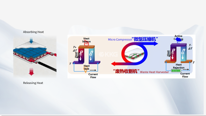
A thermoelectric cooler (TEC) is a solid-state heat pump. When current flows through the semiconductor pellets inside a Peltier module, heat is absorbed at the cold side and released at the hot side. There are no moving parts, no refrigerant, and no compressor, which makes semiconductor cooling attractive for compact instruments, laser diodes, CCD/CMOS sensors, medical cartridges, and enclosure cooling.
What a TEC cannot do is create cold. It moves heat, and it adds electrical power to that heat. The heat that must be removed from the hot side equals the heat pumped from the cold side plus the electrical input power. If that rejected heat is not removed efficiently, the hot side temperature rises, and the achievable temperature difference collapses. Understanding this single relationship explains the majority of real-world performance complaints about any thermoelectric cooler product.
Reading the Datasheet: Qmax, ΔTmax, Imax, and Vmax
Every Peltier module datasheet lists a small set of parameters. They are useful, but only if you understand the conditions under which they were measured — normally a fixed hot-side temperature such as 27°C or 50°C, and a specified mounting condition.
Qmax — maximum cooling capacity
Qmax is the maximum heat a module can pump at a temperature difference of zero. In other words, the cold side and hot side are at the same temperature, and the module is driven at its maximum rated current. Qmax is the practical ceiling on heat load, not a working value. As soon as you ask the module to create a real temperature difference, the usable cooling capacity drops, and it drops quickly at first.
ΔTmax — maximum temperature difference
ΔTmax is the largest temperature difference the module can sustain between its cold side and hot side — measured at zero heat load. Because there is no heat load, no useful work is being done. In a real application, the achievable ΔT is always lower than ΔTmax.
This is the point where many designs go wrong: Qmax and ΔTmax cannot be achieved at the same time. They sit at opposite ends of the same performance curve. A module may pump a large heat load with almost no temperature difference, or hold a large temperature difference with almost no heat load. Real operation lives somewhere between those two extremes, and the selection task is to find a module whose curve passes through your required (heat load, ΔT) point with margin.
Imax, Vmax, and electrical resistance
Imax is the current at which Qmax and ΔTmax are specified, and Vmax is the corresponding DC voltage at that same operating point. Because the module behaves electrically like a resistor with a Seebeck back-EMF, the required voltage changes with hot-side temperature and current. AC resistance measured on the datasheet is a useful first-order check of module health and helps estimate the resistive portion of power consumption.
Operating a module well below Imax is often the right engineering choice. Lower current usually improves coefficient of performance (COP), reduces thermal stress on the pellets, and can still deliver the required ΔT if the heat load is small. Maximum current is not the same as optimum current.
Matching a Thermoelectric Cooler Product to the Actual Heat Load
Before looking at any catalogue, calculate the total heat load the cold side must manage. It is almost never just the power of the device being cooled. A realistic heat load budget includes:
Active load: the electrical power dissipated by the cooled component under its worst-case operating condition, not its idle condition.
Passive load: heat conducted in through mounting hardware, wires, and the surrounding gas, plus any radiative load from nearby warm surfaces.
Transient load: short bursts such as a laser pulse, a sensor warm-up, or a thermal cycle test, which can momentarily exceed the steady-state figure.
Add these together, then add a design margin. A common practical approach is to target a heat load roughly 20–30% below the module's cooling capacity at the required ΔT, not at Qmax. That margin absorbs assembly tolerances, thermal interface material variability, and ambient excursions.
It also helps to define the cold-side setpoint precisely. Cooling from 25°C to 5°C is a 20 K lift; cooling from 25°C to −20°C is a 45 K lift and may require a different module type entirely. The larger the required temperature difference, the more the design moves toward multi-stage or higher-performance configurations.
Heat Dissipation: Where Most Thermoelectric Cooling Designs Fail
The hot side of a Peltier module is the foundation of the whole system. Heat rejected from the module equals the cold-side heat load plus the electrical power consumed by the module, so the hot side always has more heat to remove than the cold side absorbs. If the heatsink cannot remove that heat, the hot-side temperature climbs, and the achievable temperature difference falls in proportion.
Key factors to control include:
Heatsink thermal resistance: the lower, the better, and it must be evaluated at the actual airflow available — natural convection, forced air, or liquid cooling.
Thermal interface material: a thin, uniform, correctly specified interface between the module and both the heatsink and the cooled object. Poor contact here can add more thermal resistance than the module itself contributes.
Mounting pressure and flatness: uneven clamping creates hot spots and can crack ceramics. A controlled, even load across the module is essential.
Ambient temperature: a system that works at 25°C ambient may fail at 45°C, because the hot-side sink has less temperature headroom to work with.
As a rule of thumb, every degree the hot side rises costs roughly a degree of achievable cold-side temperature. Treat hot-side thermal management as a first-class design task, not an accessory decision.
Voltage, Current, and Drive Electronics
A thermoelectric cooler product is a current-driven device, but it is usually powered from a voltage source. That distinction matters. A PWM drive applied directly to a module with no filtering produces current ripple that reduces effective performance and increases heating. Linear drive or well-filtered PWM with adequate inductance is generally preferred for precision temperature control.
Temperature control strategy also influences module selection. On/off control is simple but causes thermal cycling; proportional control with a PID loop and a bipolar H-bridge allows smooth bidirectional control for applications that need both heating and cooling. If the module will be driven in heating mode, the datasheet's maximum hot-side temperature rating becomes the limiting constraint.
Also verify the supply can deliver the required voltage at Imax, accounting for cable and connector losses. Underestimating the voltage headroom is a common reason a system cannot reach its target cold-side temperature even though the module is technically capable.
Design Variants: Miniature, Multi-Stage, High-Temperature, and Custom
Standard single-stage modules cover a very wide range of thermoelectric cooling applications, but specific requirements often point to a different product family:
Miniature TEC modules suit optical components, sensors, and handheld instruments where footprint and mass matter more than raw cooling capacity.
Multi-stage (cascade) modules are used when the required temperature difference is beyond what a single stage can reach. Each stage rejects heat to the next, so overall efficiency drops, but achievable ΔT increases substantially.
High-temperature TEC modules are designed for applications where the hot side runs well above typical limits, such as industrial or automotive-adjacent environments.
Custom TEC modules allow leg geometry, ceramic type, footprint, sealing, and lead configuration to be tailored to a specific thermal and mechanical envelope — often the most efficient route once a design has matured beyond a prototype.
Frequently Asked Questions
Why does my module cool much less than its Qmax rating suggests?
Because Qmax is defined at zero temperature difference. As soon as you require a real ΔT between the cold side and hot side, available cooling capacity drops. If the hot side is also running warm because of weak heat dissipation, the loss is even larger. Always evaluate cooling capacity at your actual hot-side temperature and required ΔT.
Can I run a thermoelectric cooler product at a higher voltage to get more cooling?
Increasing voltage increases current, which raises the resistive heating term inside the module. Beyond a certain point, added Joule heating outweighs the extra Peltier pumping, and performance decreases. Modules should be operated within their rated current and voltage envelope, and often perform best at a fraction of Imax.
How do I decide between a single-stage and a multi-stage module?
Start with the required temperature difference. If it is comfortably within a single stage's practical range at your heat load and hot-side temperature, single-stage is simpler and more efficient. If it is not, multi-stage becomes necessary — but remember that each added stage increases power consumption and the amount of heat the final heatsink must remove.
Does the thermal interface material really matter that much?
Yes. A poor interface adds thermal resistance directly into the path between the module and the heatsink, raising hot-side temperature. Using an appropriate, thin, evenly applied interface material and applying correct mounting pressure often improves performance more than switching to a larger module.
How do I know whether I need a custom module?
If a standard module meets the thermal requirement but not the mechanical envelope — footprint, thickness, sealing, or lead routing — a custom thermoelectric cooler product is usually the better path. Custom designs also allow the module to be optimized for a specific hot-side temperature rather than a generic one.
Conclusion
Getting reliable performance from a thermoelectric cooler product comes down to disciplined engineering rather than wishful reading of a datasheet. Define the real heat load, decide the required temperature difference, remember that Qmax and ΔTmax describe opposite ends of the same curve, and treat hot-side heat dissipation as the limiting factor it truly is. Then choose voltage, current, and control electronics that keep the module inside its rated envelope while delivering the setpoint the application needs.
When a standard Peltier module fits the thermal and mechanical requirements, selection is straightforward. When it does not, miniature, multi-stage, high-temperature, or fully custom TEC solutions give designers the freedom to match the module to the application instead of compromising the application to fit the module. That matching process — not the module alone — is what determines whether a thermoelectric cooling system performs as intended over its service life.
META TITLE: Thermoelectric Cooler Product Selection Guide | KKG
META DESCRIPTION: Learn how to select a thermoelectric cooler product: read Qmax, ΔTmax, Imax, and Vmax correctly, manage heat load, and design reliable TEC cooling systems.
