


Selecting a Thermoelectric Cooler Premium Manufacturer for Reliable TEC Systems
Engineers searching for a Thermoelectric Cooler Premium Manufacturer usually face the same challenge: the datasheet looks simple, but real performance depends on heat load, hot-side temperature, heatsink behavior, and the operating point. A premium supplier should help you move from a rough concept to a validated TEC design, not just quote a Peltier module. This guide explains the engineering criteria that matter when selecting a thermoelectric cooling partner and specifying a TEC module for a real application.
Begin With the Heat Load and Thermal Path
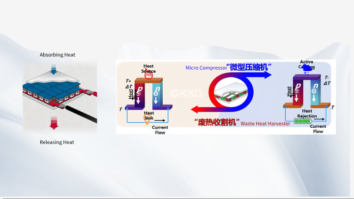
A thermoelectric cooler does not create cooling in isolation. It moves heat from the cold side to the hot side using semiconductor cooling, and the hot side must reject both the pumped heat load and the electrical input power. This is why TEC selection should start with an energy balance, not a module size. Define the heat load in watts, the target cold-side temperature, the expected ambient temperature, and the available hot-side heat dissipation method. Include conduction, convection, radiation, and any transient loads if the application cycles on and off.
The thermal path matters as much as the TEC module itself. Thermal interface material, mounting pressure, surface flatness, insulation, and heatsink thermal resistance all affect the temperature difference that the system can hold. A low thermal resistance path on the cold side helps couple the load to the Peltier module; a strong hot-side path keeps the hot side close to ambient. If either side is weak, the TEC may draw full current while the cold side never reaches target temperature.
Read Qmax, ΔTmax, Imax, and Vmax as Datasheet Limits
Datasheets usually list Qmax, ΔTmax, Imax, and Vmax, but these numbers are not a guaranteed operating point. Qmax is the maximum cooling capacity, normally specified at zero temperature difference between the cold side and hot side. ΔTmax is the maximum temperature difference, normally specified at zero heat load. Imax and Vmax are maximum current and voltage limits under specified conditions. In a real application, a TEC does not deliver Qmax and ΔTmax at the same time. The actual cooling capacity depends on the temperature difference, hot-side temperature, input voltage, input current, and the thermal resistance of the complete assembly.
This distinction is central to TEC selection. If an application needs a large temperature difference, the available cooling capacity falls. If it needs high cooling capacity, the temperature difference must usually be smaller. A premium manufacturer should provide performance curves or application support that shows how the module behaves across the relevant range, not only the headline maximum values. When comparing Peltier cooler options, ask for the operating point that matches your heat load and target temperatures.
What a Thermoelectric Cooler Premium Manufacturer Should Help You Define
A Thermoelectric Cooler Premium Manufacturer should add engineering value before production. The useful discussion is not only about price per module; it is about whether the TEC module fits the thermal management strategy. A supplier should ask about heat load, ambient conditions, target cold-side temperature, allowable hot-side temperature, available voltage and current, duty cycle, condensation risk, mechanical envelope, and expected service life. These inputs determine whether a single-stage TEC, multi-stage TEC, miniature TEC, or custom TEC is a reasonable starting point.
For example, a miniature TEC may suit a compact optical or sensor package where space is tight, but the small area can make heat dissipation more difficult. A multi-stage TEC can achieve a larger temperature difference, but it usually has lower efficiency and requires careful hot-side management. A custom TEC may be appropriate when the mechanical outline, sealing, or electrical connection must match an existing enclosure. The right choice is the one that satisfies the thermal and mechanical constraints together, not the one with the largest printed Qmax.
Match Voltage, Current, and Power Consumption to the System
Voltage and current selection affects the power supply, wiring, control electronics, and total power consumption. The TEC electrical resistance, Imax, and Vmax define limits, but the operating voltage and current should be chosen around the required cooling capacity at the target temperature difference. Running a module at a higher current is not automatically better. It can increase Joule heating inside the module and raise power consumption faster than it raises useful cooling capacity, especially when the hot side is not well controlled.
For battery-powered or sealed systems, power consumption and heat rejection become part of the same design problem. The hot-side heatsink must remove the heat load plus the electrical input power. If the heatsink is undersized, the hot side rises, the temperature difference grows, and the TEC works less effectively. This is a common reason a Peltier cooler appears to underperform even when the module itself is within specification. In many designs, improving heat dissipation is more effective than increasing TEC current.
Treat Hot-Side Temperature and Thermal Resistance as Design Variables
The hot side is not a secondary detail. It sets the reference temperature for the cold side. A lower hot-side temperature generally allows a larger useful temperature difference and more stable cooling capacity. The heatsink, fan, cold plate, thermal interface material, and ambient airflow all contribute to the hot-side thermal resistance. Natural convection may be adequate for a low-power enclosure, while a forced-air heatsink or liquid loop may be necessary when heat flux is higher. The choice should be based on the actual thermal resistance and ambient conditions, not on a rule of thumb.
Condensation is another practical issue. When the cold side drops below the dew point, moisture can form on the cold surface, in the insulation, or around electrical connections. A premium TEC design should consider sealing, insulation, drainage, and control strategy. These are not module specifications, but they influence whether the thermoelectric cooling system works reliably in the field. The same is true for installation: uneven mounting pressure, poor surface contact, or degraded thermal interface material can raise thermal resistance and reduce performance over time.
Validate the TEC Design Under Real Operating Conditions
After selecting a TEC module, validate the assembly with the intended heat load, ambient temperature, voltage, current, and control method. Measure cold-side temperature, hot-side temperature, input power, and cooling capacity at steady state. If the target is not reached, check the hot-side heat dissipation first, then the thermal interface, insulation, and heat load assumptions. A TEC that performs well on a bench with an open heatsink may behave differently inside a sealed enclosure where ambient air rises.
Engineering support from a manufacturer should include practical questions about tolerances, mounting, lead routing, and reliability. Avoid treating the TEC as a drop-in part without checking the thermal system around it. The most successful projects usually combine a properly specified Peltier module with a realistic thermal path, adequate heat dissipation, and a control strategy that respects the module limits.
Frequently Asked Questions
Can Qmax and ΔTmax be achieved at the same time?
No. Qmax is normally specified at zero temperature difference, while ΔTmax is normally specified at zero heat load. In a real system, cooling capacity falls as the temperature difference increases. Use performance curves or application data for the intended operating point.
Why does my thermoelectric cooler not reach the target temperature?
Common causes include insufficient hot-side heat dissipation, high thermal resistance in the cold-side path, an underestimated heat load, poor thermal interface contact, or excessive ambient temperature. Check the complete thermal path before changing the TEC module.
When should I consider a multi-stage TEC?
A multi-stage TEC may be considered when the application needs a large temperature difference and the heat load is relatively small. It is not automatically more efficient; multi-stage designs can have lower cooling efficiency and require careful hot-side thermal management.
What information should I provide to a TEC supplier?
Provide heat load, target cold-side temperature, expected hot-side and ambient conditions, available voltage and current, mechanical envelope, duty cycle, condensation risk, and any control or reliability requirements. This helps the supplier recommend a suitable TEC module or custom design direction.
Conclusion
Selecting a Thermoelectric Cooler Premium Manufacturer is ultimately a thermal engineering decision. The module must match the heat load, temperature difference, voltage and current limits, and heat dissipation strategy, while the supplier should help interpret Qmax, ΔTmax, Imax, and Vmax correctly. A TEC that is specified around the real operating point, supported by a low thermal resistance path and adequate hot-side cooling, is more likely to meet performance targets than a module chosen only by headline maximum ratings. For reliable thermoelectric cooling, design the system around the application, then select the Peltier cooler that fits it.
META TITLE: Thermoelectric Cooler Premium Manufacturer Selection Guide
META DESCRIPTION: Learn how to evaluate a Thermoelectric Cooler Premium Manufacturer, read Qmax, ΔTmax, Imax, and Vmax, and design reliable TEC thermal management.