


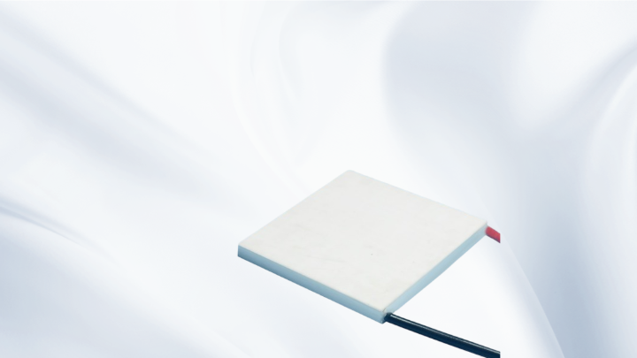
Durable Thermoelectric Generator Chip: Selection, Thermal Design, and Reliability Guide
What "Durable" Actually Means in a Durable Thermoelectric Generator Chip
In thermoelectric power generation, the word durable is often used loosely. For an engineer, it describes a specific set of behaviors: stable output over thousands of thermal cycles, no cracking of the ceramic substrates, no solder or sinter joint fatigue, and no measurable increase in internal resistance after long-term operation at temperature. A durable thermoelectric generator chip is therefore not defined by a single datasheet number, but by how well its construction tolerates the environment it will actually face.
A thermoelectric generator (TEG) converts a temperature difference into electrical power through the Seebeck effect. Heat flows from the hot side to the cold side through the thermoelements, and the resulting voltage appears across the module terminals. Some of that heat flow is converted into electricity; the rest must be rejected to the ambient. This means a TEG module is simultaneously an electrical device and a thermal device, and durability problems almost always originate on the thermal and mechanical side rather than in the semiconductor material itself.
Common causes of premature failure include thermal cycling fatigue, coefficient of thermal expansion (CTE) mismatch between ceramics, solder, and thermoelements, excessive clamping pressure, inadequate heat dissipation, and oxidation at elevated hot-side temperatures. Each of these is addressed during design, not after installation.
Key Parameters to Evaluate in a Durable Thermoelectric Generator Chip
When reviewing a TEG datasheet, engineers should focus on a small number of parameters and understand how they interact.
Seebeck Coefficient and Open-Circuit Voltage
The Seebeck coefficient (α) relates the temperature difference across the module to the open-circuit voltage, approximately Voc = α × ΔT for a single couple, multiplied across the number of couples in series. Higher ΔT generally means more voltage, but the achievable ΔT is limited by the thermal stack, not by the module alone.
Internal Resistance
Internal electrical resistance determines how much current the module can deliver and how much Joule heating is generated internally. A rising internal resistance over time is one of the clearest indicators of joint degradation, so resistance stability is a practical durability metric.
Matched Load and Power Output
Maximum power transfer occurs when the load resistance matches the module's internal resistance. Electrical power at matched load is approximately P = (α × ΔT)² / (4R). In practice, a maximum power point tracking (MPPT) DC-DC converter is used because the internal resistance shifts with temperature.
Thermal Conductance
Thermal conductance describes how much heat passes through the module per degree of temperature difference. It directly affects how much heat must be supplied by the source and how much must be removed by the cold-side heatsink.
For engineers who also work with cooling modules, datasheets use a different parameter set — Qmax, ΔTmax, Imax, and Vmax — which describe a Peltier cooler's maximum performance envelope. It is important to remember that Qmax and ΔTmax are not achieved at the same operating point: Qmax corresponds to zero temperature difference, while ΔTmax corresponds to zero heat load. The same logic of trade-offs applies to generator modules, where maximum power and maximum efficiency occur at different operating conditions.
Thermal Design: The Deciding Factor for Durable Thermoelectric generator chip Performance
The thermal path from heat source to ambient determines both power output and long-term reliability. The stack typically includes the heat source interface, thermal interface material (TIM), hot-side ceramic, thermoelements, cold-side ceramic, a second TIM layer, and the heatsink.
Each layer contributes thermal resistance. Total thermal resistance limits the temperature difference that can be sustained: ΔT = Q × Rtotal, where Q is the heat flow. If the cold-side heatsink cannot reject heat efficiently, the cold-side temperature rises, ΔT collapses, and the module produces little power while still enduring thermal stress.
Practical design rules include:
1. Size the heatsink for the total heat flow, not just the electrical output. Most of the heat entering a TEG passes through it rather than being converted, so the heatsink must handle a heat load far larger than the generated power.
2. Keep the hot side within the material's rated limit. Module construction — solder type, sintered joints, ceramic grade — sets a maximum continuous hot-side temperature. Exceeding it accelerates diffusion and oxidation.
3. Minimize interface resistance. Thermal grease, graphite sheets, or phase-change pads reduce contact resistance, but they must be stable at the operating temperature. A TIM that dries or pumps out will slowly degrade performance.
4. Control the cold side. Natural convection, forced air, and liquid cooling each provide different thermal resistance. Selecting the weakest option that meets the target usually produces the longest service life, because it reduces thermal cycling amplitude.
Mechanical and Material Considerations for Long Service Life
A durable thermoelectric generator chip survives mechanical stress as well as thermal stress. Several factors deserve attention during mounting.
Clamping Pressure and Flatness
Modules are typically clamped between the heat source and heatsink. Too little pressure increases contact resistance; too much pressure can crack ceramic substrates. Flatness of the mating surfaces matters as much as the force applied, because uneven loading concentrates stress at the edges of the thermoelements.
Thermal Cycling and Ramp Rates
Repeated heating and cooling produces fatigue at the joints. Controlled ramp rates, a compliant interface layer, and avoiding frequent full-range cycles all extend life. Where the application involves intermittent heat — for example, exhaust-driven or process-driven generation — designing for a limited cycle depth is more effective than attempting to eliminate cycling entirely.
Environmental Protection
Moisture, condensation, and corrosive atmospheres attack metallization and interconnects. Encapsulation, sealed housings, or conformal coatings protect the module when the environment cannot be controlled.
Application Scenarios Where Durability Dominates
Industrial waste-heat recovery, remote sensor power, exhaust-based energy harvesting, and off-grid monitoring systems all share one characteristic: maintenance access is difficult or impossible. In these cases, a modular approach using proven thermoelectric building blocks — including multi-stage TEC/TEG assemblies, high-temperature modules, and custom thermoelectric assemblies — allows the thermal stack to be matched precisely to the source, which usually matters more than squeezing out the last few percent of conversion efficiency.
For low-power sensing applications, a miniature thermoelectric generator chip paired with a small heatsink and an MPPT converter can power wireless nodes from modest temperature differences. Here durability is driven by the stability of the thermal contact over years of unattended operation.
Frequently Asked Questions
How long should a durable thermoelectric generator chip last?
Service life depends on hot-side temperature, cycle depth, mounting quality, and environmental protection. Modules operated well within their rated temperature limits, with stable clamping and protected interfaces, typically outlast the electronics they power. Extremes of temperature and rapid cycling are the main life-shortening factors, not the thermoelectric material itself.
Why does my TEG output drop over time even though nothing has changed?
The most common causes are increasing contact thermal resistance from a degraded thermal interface material, loosened clamping hardware, oxidation on the hot-side metallization, or a rising internal electrical resistance caused by joint fatigue. Measuring open-circuit voltage and internal resistance periodically is the simplest way to separate thermal degradation from electrical degradation.
Is a larger temperature difference always better for power output?
Larger ΔT increases voltage but also increases thermal stress and accelerates aging mechanisms. Beyond the module's rated hot-side temperature, output gains are quickly offset by reliability losses. The practical optimum is the highest ΔT that keeps both hot-side and cold-side conditions within the module's design envelope.
Can I use a standard Peltier module as a generator?
Yes, thermoelectric modules operate in both modes, but performance and durability differ. Generator modules are usually built with materials and joints selected for continuous high-temperature operation. A Peltier cooler used as a generator will work at small ΔT, but its rated hot-side temperature and joint construction may limit long-term reliability.
How do I improve the durability of an existing design?
Start with the thermal stack: verify clamping pressure and surface flatness, replace dried or pumped-out interface material, confirm the heatsink can reject the full heat load, and reduce thermal ramp rates where possible. These measures typically deliver more reliability improvement than changing the module itself.
Conclusion
Selecting a durable thermoelectric generator chip is a system-level decision. The module's material system, joint construction, and rated hot-side temperature define the envelope, but the achievable temperature difference, power output, and service life are determined by the surrounding thermal path — heatsink capacity, interface resistance, clamping method, and cycling profile. Engineers who treat the TEG as one element in a complete thermal management design, rather than a standalone component, consistently achieve more stable output and longer field life. Working with a manufacturer that understands both cooling and generation applications makes it easier to match the module, the thermal stack, and the operating conditions to the real-world requirement.
Meta Title: Durable Thermoelectric Generator Chip | Design Guide
Meta Description: Learn how to select and design with a durable thermoelectric generator chip: thermal resistance, matched load, hot-side limits, and mounting best practices.